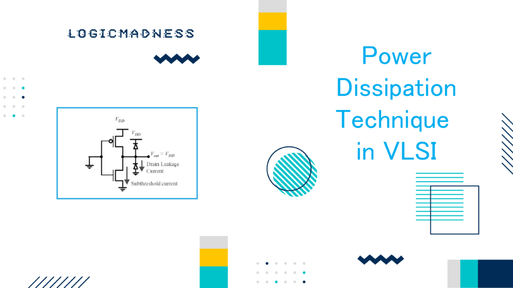
Power management is essential in VLSI design to improve efficiency, extend battery life, and reduce overall energy consumption. Understanding the sources of power dissipation and applying effective management techniques can help achieve a high-performance, low-power design. This guide covers the fundamentals of power dissipation, key power management techniques, and important UPF (Unified Power Format) commands used in low-power VLSI design.
Power Dissipation in VLSI Circuits
1. Sources of Power Dissipation
Power dissipation in VLSI circuits occurs mainly due to static and dynamic power. Here’s a brief overview:
| Power Type | Description |
| Static Power | Power consumed even when the circuit is idle, primarily due to leakage current. |
| Dynamic Power | Power used during switching of transistors; includes both switching power and short-circuit power. |
2. Static Power
Static power arises from leakage currents in the transistors, even when they are not switching. As transistors scale down, leakage increases, contributing significantly to power dissipation in modern designs.
3. Dynamic Power
Dynamic power is the power consumed during active switching of transistors and can be categorized into two types:
- Switching Power: Power dissipated due to charging and discharging of load capacitances.
- Short-Circuit Power: Power consumed due to the brief short circuit that occurs when both PMOS and NMOS transistors are on during switching.
Common Power Management Techniques
VLSI circuits incorporate various power management strategies to reduce power dissipation effectively. Some widely used techniques include:
1. Multi Vth Design
- Multi Vth (threshold voltage) design employs transistors with different threshold voltages in the same circuit. This helps in balancing speed and leakage power.
2. Bus Encoding
- Redundant Encoding: Reduces the switching activity by encoding data to reduce transitions, lowering dynamic power.
- Non-Redundant Encoding: Uses techniques like gray coding to achieve a similar effect without adding extra bits.
3. Hardware-Software Tradeoff
- Balances computational workload between hardware and software to reduce power and optimize performance.
4. Multi Vdd Design
- SVS (Static Voltage Scaling): Applies different static voltage levels across various components.
- DVFS (Dynamic Voltage and Frequency Scaling): Dynamically adjusts voltage and frequency based on workload, saving power when the circuit is idle or under light loads.
5. Clock Gating
- Disables the clock signal to idle portions of the circuit, saving power by reducing unnecessary switching.
6. Power Gating
- Power gating disconnects the power supply to sections of the circuit not in use, minimizing leakage power in inactive blocks.
Multi-Voltage and Multi-Power Domain Design
Multi-voltage domains and power domains introduce additional complexities but allow finer control over power usage in VLSI circuits.
1. Isolation Cells and Level Shifter Cells
Isolation cells and level shifter cells help manage different power and voltage domains within a design:
- Isolation Cells: Used to prevent unwanted signal propagation between power domains.
- Level Shifters: Adjust voltage levels between different voltage domains, ensuring compatibility and preventing errors.
| Component | Purpose |
| Isolation Cells | Isolate signals between different power domains to prevent unintended propagation. |
| Level Shifters | Adjusts voltage levels between domains, ensuring signal compatibility across power domains. |
2. Retention Cells
Retention cells are used to store data when parts of the circuit are powered down. Retention cells are crucial in power-gated domains to save critical data.
- Types of Retention Cells: Common retention types include master-slave alive retention flops which retain data across power-down cycles.
3. Clamping Concept in Isolation
Clamping ensures that the output from an inactive domain is held at a known state, preventing unpredictable behavior in downstream logic.
Unified Power Format (UPF) Commands for Power Intent
The UPF standard helps define power management intentions and strategies for VLSI design. Here are some of the commonly used UPF commands:
| UPF Command | Purpose |
| create_power_switch | Defines a power switch for power-gated sections. |
| set_isolation | Configures isolation logic between different power domains. |
| set_isolation_control | Sets the control signals for isolation cells. |
| set_level_shifter | Defines level shifters between voltage domains. |
| set_retention | Specifies retention strategies for data preservation during power-down states. |
| set_retention_control | Configures control signals for retention flops. |
| add_port_state | Adds a power state to a specific port. |
| create_pst | Creates a power state table to define power states across various power domains. |
| add_pst_state | Adds power states to the power state table, enabling specific states under different conditions. |
Writing UPF for Power Intent
When writing a UPF, it is crucial to:
- Define each power domain and associated switches.
- Specify isolation and level shifter requirements.
- Set up retention strategies for critical data.
- Configure power states and conditions for transitions.
Comparison of Power Management Techniques
Here’s a comparison of popular power management techniques to help understand their specific benefits:
| Technique | Key Benefit | Application Domain |
| Multi Vth Design | Balances speed and leakage | High-speed and low-power areas |
| Bus Encoding | Reduces dynamic power | Data buses, interconnects |
| Clock Gating | Saves power by disabling unused sections | Entire circuit |
| Power Gating | Reduces leakage power | Idle or inactive circuit blocks |
| Isolation Cells | Ensures correct signal flow | Multi-power domain designs |
| Level Shifters | Adjusts cross-domain voltages | Multi-voltage domain designs |
By strategically implementing these power management techniques, designers can achieve optimized area, power, and performance in VLSI designs. Proper UPF command use further ensures consistent power management across complex designs.

