Power dissipation is a critical aspect of VLSI (Very Large Scale Integration) design, impacting both performance and energy efficiency. Understanding the sources of power dissipation is essential for engineers and designers to create effective, low-power circuits. This article explores the two main types of power dissipation: Static Power and Dynamic Power.
Sources of Power Dissipation
Power dissipation in VLSI circuits can be broadly classified into two categories:
| Type of Power Dissipation | Description |
| Static Power | Power consumed when the circuit is inactive (quiescent mode). |
| Dynamic Power | Power consumed during circuit operation (active mode). |
Static Power
Static power dissipation occurs when the circuit is not actively switching, yet it still consumes power due to leakage currents. These currents flow even when the circuit inputs are not changing and the clock is off. The key aspects of static power include:
- Leakage Currents: The primary cause of static power consumption. When a transistor is off, leakage currents can still flow through it. Two common types of leakage currents are:
- Reverse Bias Leakage Current: Occurs when the junction diodes in the transistors are reverse biased.
- Sub-threshold Leakage Current: Flows from the drain to source when the gate-source voltage (VGS) is below the threshold voltage (Vth).

Note: Typically, the leakage power dissipation is inversely proportional to the transistor’s threshold voltage (Vth).
Dynamic Power
Dynamic power dissipation occurs when the circuit is actively switching. This type of power is primarily due to dynamic currents resulting from two main sources:
Switching Power Dissipation
Switching power is the energy consumed during the charging and discharging of capacitors in the circuit. The formula for switching power dissipation (Pswitch) can be expressed as:
Pswitch = α ⋅ (Vdd)2 ⋅ CL ⋅ f
Where:
- α = Switching activity (probability of the output transitioning between 0 and 1).
- Vdd = Supply voltage.
- CL = Total load capacitance.
- f = Frequency of operation.
Understanding Switching Activity:
- If the signal is a clock signal, α is 1.
- If the output changes once per clock cycle, α is 0.5.
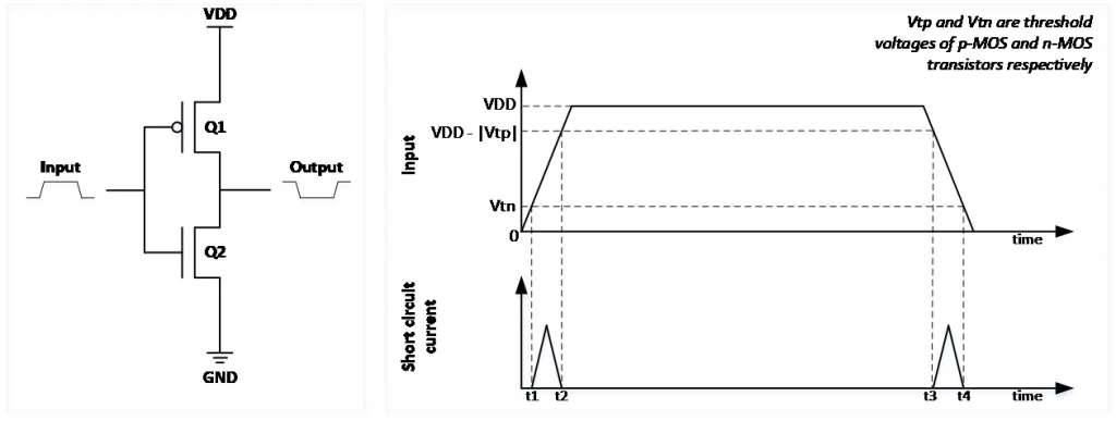
Short-Circuit Power Dissipation
Short-circuit power dissipation occurs when both the pull-up and pull-down transistors in a circuit are on simultaneously during the transition period, creating a direct path from the supply voltage (VDD) to ground (GND). This typically happens when the input changes slowly, causing a brief overlap in the states of the transistors.
Example: Consider an inverter circuit, where during specific time intervals (e.g., between t1 & t2 and t3 & t4), both transistors Q1 and Q2 can be turned on, resulting in short-circuit current flow.
Conclusion
Understanding power dissipation is vital for designing efficient VLSI circuits. By addressing both static and dynamic power sources, engineers can significantly enhance performance while minimizing energy consumption. Implementing techniques such as voltage scaling, clock gating, and optimizing circuit designs can lead to more efficient power management in VLSI systems.
Additional Power Management Techniques
| Technique | Description |
| Multi Vth Design | Uses transistors with multiple threshold voltages to optimize power. |
| Bus Encoding | Redundant and non-redundant methods to reduce switching activities. |
| Multi Vdd Design | Techniques like SVS (Supply Voltage Scaling) and DVFS (Dynamic Voltage and Frequency Scaling) to optimize power usage. |
| Clock Gating | Disabling the clock to parts of the circuit that are not in use. |
| Power Gating | Disconnecting power from sections of the circuit to reduce leakage. |
| Isolation Cells | Used to prevent unwanted current flow between power domains. |
| Retention Cells | Maintain state during power gating to preserve data integrity. |
Key UPF Commands for Power Intent Specification
- create_power_switch: Define a power switch in the circuit.
- set_isolation: Specify isolation parameters.
- set_retention: Configure retention settings for cells.
- add_port_state: Add states for ports to control power management.