The Advanced Peripheral Bus (APB) is a protocol from the Advanced Microcontroller Bus Architecture (AMBA) family, primarily used for low-bandwidth peripherals. The latest version of APB is 2.0, introduced with the AMBA 4 release. APB is designed to offer low-cost and efficient communication, with a focus on minimizing power consumption and simplifying the interface.
Unlike other bus protocols like AHB (Advanced High-performance Bus), APB operates as a non-pipelined protocol. It connects low-bandwidth peripherals to a system-on-chip (SoC) and typically requires at least two clock cycles (SETUP Cycle and ACCESS Cycle) to complete a transfer. APB can also interface with AHB and AXI protocols via bridge components.
APB in a System-on-Chip (SoC)
The APB_soc diagram below illustrates how APB fits into a typical system architecture. The central component of this system is the high-performance ARM processor. Other high-bandwidth components, like RAM and DMA controllers, are connected to the ARM core via the AHB system bus. Low-bandwidth peripherals like UART, timers, keypads, and PIOs are connected through a bridge to the APB bus.
In this setup, the AHB to APB bridge acts as the APB master, controlling the transfer of data to low-bandwidth peripherals. This configuration ensures the system maintains high performance while managing simpler peripheral devices.
Key Components and Signal Description
Below is a detailed explanation of the main signals in the APB protocol, as shown in the block diagram:
| Signal | Description |
|---|---|
| PCLK | System clock that drives the timing of the protocol. |
| PRESETn | Active low reset signal to initialize the system. |
| PADDR[31:0] | Address bus that carries the address from the master to the slave (up to 32 bits). |
| PWDATA[31:0] | Write data bus that carries data from the master to the slave (up to 32 bits). |
| PRDATA[31:0] | Read data bus that carries data from the slave to the master (up to 32 bits). |
| PSELx | Slave select signal that identifies the target slave in the system. |
| PENABLE | Indicates the beginning of the access phase. |
| PWRITE | Indicates a write operation (HIGH) or read operation (LOW). |
| PREADY | Used by the slave to request wait states if it cannot complete the transfer. |
| PSLVERR | Indicates the success (LOW) or failure (HIGH) of the transfer. |
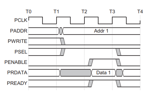
Understanding APB Write and Read Transfers
Write Transfer Without Wait States
In a typical APB write transfer without wait states, the process unfolds as follows:

- Setup Phase (T1): The master provides the address (PADDR), write data (PWDATA), and control signals.
- Access Phase (T2): After the next rising edge of PCLK, the slave acknowledges the start of the access phase with the PENABLE signal.
- The master ensures that all signals remain stable until the transfer completes at T3.
Write Transfer With Wait States

When the slave needs more time, it can assert PREADY low, indicating it isn’t ready to complete the transaction. The master must hold the signals stable while PREADY is low. Once PREADY goes high, the transfer proceeds to completion.
Read Transfer Without Wait States
In a typical APB read transfer, the following steps occur:
- Setup Phase (T1): The master initiates the read request with PADDR and control signals.
- Access Phase (T2): The slave begins the read transfer by providing the requested data (PRDATA).
- The data must be ready before the end of the transfer (T3).
Read Transfer With Wait States

When the slave can’t provide the data immediately, it drives PREADY low during the access phase, extending the transfer until it’s ready to send the data. The master should hold all signals stable during this period.
Error Handling in APB Protocol
Error Response for a read transfer:

Error Response for a write transfer:

In case of errors during a transaction, the PSLVERR signal is used. This signal indicates an error response when the transfer is complete (during the last cycle). If an error occurs, it is not guaranteed that the data was successfully written or read. For example, if a write transaction encounters an error, the data may not be written to the slave device.
| Transfer Type | Error Response |
|---|---|
| Write | APB_Write_Error |
| Read | APB_Read_Error |
Protection Unit Support in APB Protocol
To enhance system security, APB includes protection mechanisms. These are governed by the PPROT signals, which provide three levels of access control:
| PPROT[2:0] | Description |
|---|---|
| PPROT[0] | LOW = Normal Access, HIGH = Privileged Access |
| PPROT[1] | LOW = Secure Access, HIGH = Non-Secure Access |
| PPROT[2] | LOW = Data Access, HIGH = Instruction Access |
These signals help prevent illegal transactions within the system.
Operating States of APB Protocol
The APB Protocol operates in three primary states:

- IDLE State: This is the default state where the bus is inactive.
- SETUP State: When a transfer is requested, the bus enters the SETUP state. This lasts for just one clock cycle.
- ACCESS State: The bus enters the ACCESS state once PENABLE is asserted. During this state, the address, write, and data signals must remain stable.
| Operating State | Description |
|---|---|
| IDLE | Default, no activity. |
| SETUP | Bus moves to setup state for one clock cycle. |
| ACCESS | Data transfer occurs; signals remain stable. |
APB Protocol RTL Code
// Code your design here
module AMBA_APB(P_clk,P_rst,P_addr,P_selx,P_enable,P_write,P_wdata,P_ready,P_slverr,P_rdata);
  //input configration
  input P_clk;
  input P_rst;
  input [31:0]P_addr;

  input P_selx;
  input P_enable;
  input P_write;
  input [31:0]P_wdata;

  //output configration
  output reg P_ready;
  output reg  P_slverr;
  output reg [31:0]P_rdata;
  //memory decleration
  reg [31:0]mem[31:0];
  //state declaration communication
  parameter [1:0] idle=2'b00;
  parameter [1:0] setup=2'b01;
  parameter [1:0] access=2'b10;

  //state declaration of present and next
  reg [1:0] present_state,next_state;

  always @(posedge P_clk) begin
    if(P_rst) present_state <= idle;
    else
      present_state <= next_state;
  end
  always @(*) begin
  //next_state =present_state;
  case (present_state)
    idle:begin
      if (P_selx   & !P_enable)
				next_state = setup;
      P_ready=0;
    end

    setup:begin if (!P_enable | !P_selx)
						next_state = idle;
              else begin
						next_state =access;

                if(P_write ==1) begin
                  mem[P_addr]= P_wdata;
                  P_ready=1;
                  P_slverr=0;
                   end
                 else begin
                   P_rdata=mem[P_addr];
                   P_ready=1;
                   P_slverr=0;
                 end
               end
    end
    access :begin
      if (!P_enable | !P_selx) begin
					    next_state = idle;
                        P_ready =0;
             end
    end
	endcase
end
endmodule
Testbench of APB Protocol
module tb;
  //input configration
  reg P_clk;
  reg P_rst;
  reg [31:0]P_addr;

  reg P_selx;
  reg P_enable;
  reg P_write;
  reg [31:0]P_wdata;

   //output configration
  wire  P_ready;
  wire  P_slverr;
  wire [31:0]P_rdata;

  //intantiation of all port
  AMBA_APB  dut1(P_clk,P_rst,P_addr,P_selx,P_enable,P_write,P_wdata,P_ready,P_slverr,P_rdata);

  always #5 P_clk=~P_clk;

  task initialization;
    begin
      P_clk=0;
      P_rst=0;
      P_addr=0;
      P_selx=0;
      P_enable=0;
      P_write=0;
    end
  endtask
   // task reset.
  task reset;
    begin
      P_rst=1;
      #10 P_rst=0;
    end
  endtask


  task write_stimulus;
    begin
      @(posedge P_clk);
      P_selx=1;
      P_write=1;
      P_wdata={$random}%10;
      P_addr=P_addr+1;

      @(posedge P_clk);
      P_enable=1;
      P_selx=1;
      @(posedge P_clk);
      P_enable=0;
      P_selx=0;

      @(posedge P_clk);
      $strobe ("writing data into memory data_in=%0d adress_in=%0d" , P_wdata,P_addr);
    end
  endtask

   task read_stimulus;
    begin
      @(posedge P_clk);
       P_write=0;
       P_selx=1;
       P_enable=0;
      //P_addr=P_addr+1;
      @(posedge P_clk);
      P_enable=1;
      P_selx=1;
      P_addr<=P_addr+1;
      @(posedge P_clk);
      P_enable=0;
      P_selx=0;

      @(posedge P_clk);
      $strobe("reading data from memory data_out=%0d   address_out=%0d",P_rdata,P_addr);
    end
  endtask

   task read_write;
  begin
    repeat(2) begin
      write_stimulus;
    end
    #1
    P_addr=0;
    repeat(3) begin
      read_stimulus;
    end
  end
  endtask

    initial begin
    $dumpfile("dump.vcd");
    $dumpvars;
    initialization;//initialize input values
    reset;// generate signal
    read_write;
     #80; $finish;
  end
endmodule
Conclusion: Key Takeaways About the APB Protocol
The APB Protocol offers a simple and efficient solution for connecting low-bandwidth peripherals in a system. By using low power and reducing complexity, it serves as an essential component in modern SoCs. The protocol’s operation, including its write and read transfer procedures, error handling, and protection mechanisms, ensures reliable and secure communication within a system.
By implementing a bridge between AHB and APB, APB seamlessly integrates with high-performance buses, making it a versatile and indispensable protocol in embedded system design.
